Welding Cart Build Plan: Drawing, Cut List and Assembly
A three-shelf welding cart built from 1.5” square tube (11 ga, 0.120” wall), with 3/4” plywood on every shelf, 16” of clear height above each shelf, and an 8” extension on the bottom shelf for the gas tanks. All joints are butt joints. The columns run flush to the top of the top rails, and the open column tops are covered by the top plywood.
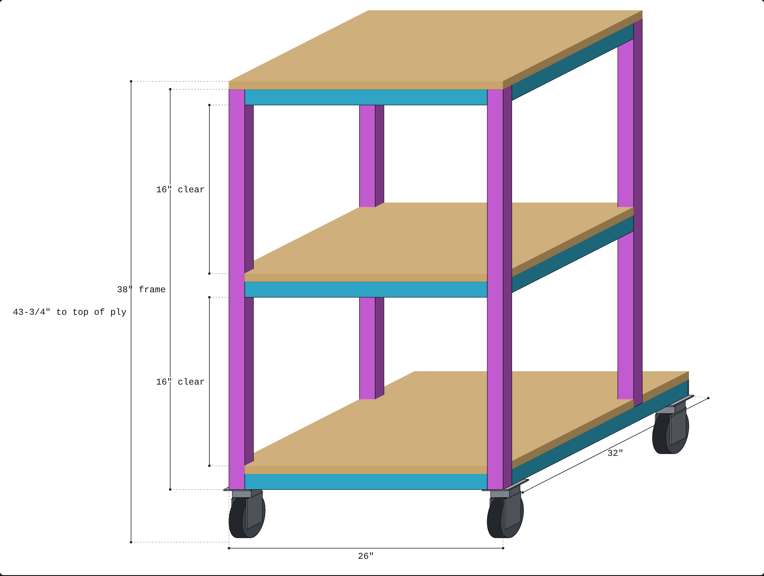
Overall dimensions
| Item | Size |
|---|---|
| Width | 26.0” |
| Depth, front column face to rear column face | 24.0” |
| Depth, bottom shelf including tank extension | 32.0” |
| Frame height, bottom of bottom rail to top of top rail | 38.0” |
| Height to top of top plywood | 38.75” |
| Height to top of top plywood on 5” casters | 43.75” |
| Clear opening above each plywood shelf | 16.0” |
Heights, measured up from the bottom of the frame
| Level | From | To |
|---|---|---|
| Bottom rails and bottom side rails | 0.00” | 1.50” |
| Bottom plywood | 1.50” | 2.25” |
| Lower opening | 2.25” | 18.25” |
| Mid rails and mid side rails | 18.25” | 19.75” |
| Mid plywood | 19.75” | 20.50” |
| Upper opening | 20.50” | 36.50” |
| Top rails and top side rails | 36.50” | 38.00” |
| Top plywood | 38.00” | 38.75” |
Cut list
| Part | Qty | Length | Notes |
|---|---|---|---|
| Front column | 2 | 38.00” | Notch at the bottom rail only. The top is left open and covered by the plywood. |
| Rear column | 2 | 36.50” | Plain square cuts. Sits on top of the bottom side rail. Top left open. |
| Front bottom rail | 1 | 25.76” | Width minus 2 x 0.120” wall. Fits between the column outer-wall tabs. |
| 23” rail | 6 | 23.00” | Front top, rear top, front mid, rear mid, rear bottom, and back cross rail. Each butts between two faces 23” apart. |
| Bottom side rail | 2 | 30.50” | Front frame to the rear end of the tank shelf. The open rear end gets a cap. |
| Top and mid side rail | 4 | 21.00” | Two top, two mid. Each butts between the front and rear columns. |
| Plywood, top shelf | 1 | 26” x 24” | 3/4”. No notches. |
| Plywood, mid shelf | 1 | 26” x 24” | 3/4”. Notch all four corners 1.5” x 1.5”. |
| Plywood, bottom shelf | 1 | 26” x 32” | 3/4”. Notch the two front corners 1.5” x 1.5”, and cut a 1.5” x 1.5” notch in each side edge at the rear columns. |
| Caster | 4 | 4” wheel | Swivel, about 5” overall height (assumed). |
Total tube is 457.76” in 17 pieces.
Bar plan, 10’ (120”) stock
Four bars cover it. The plan assumes a 1/8” saw kerf and holds back 1/2” per bar for squaring the rough ends. Cut each bar from the longest piece to the shortest.
| Bar | Cuts | Drop |
|---|---|---|
| 1 | Front column 38.00, front column 38.00, rear column 36.50 | 7.25” |
| 2 | Rear column 36.50, bottom side rail 30.50, bottom side rail 30.50, side rail 21.00 | 1.13” |
| 3 | Front bottom rail 25.76, 23” rail x 4 | 1.74” |
| 4 | 23” rail x 2, side rail 21.00 x 3 | 10.50” |
Bar 2 is the tight one. If your kerf is wider than 3/16”, cut that bar first.
The plywood comes out of one 4’ x 8’ sheet. Rip a 26” strip, then cut 24” + 24” + 32” from it (80” of the 96” length).
Assembly
Work on a flat table. Tack everything first, check square, then finish welding.
- Cut and deburr every piece to the bar plan.
- Notch the front columns. At the bottom end of each front column, cut a notch 1.5” tall and 1.38” deep (1.5” minus the 0.12” wall) from the inside. Remove the front, back and inner walls over that height. Only the outer wall remains, as a 0.12” tab. The two columns are mirror images.
- Build the front frame, laid flat. Set the two front columns 26” apart, outside to outside. Fit the 25.76” front bottom rail between the tabs, flush with the column bottoms. Fit a 23” rail flush with the column tops for the top rail. Fit a 23” rail between the column inner faces with its bottom 18.25” above the column bottom, for the mid rail. Check that the diagonals match, then weld.
- Build the rear frame, laid flat. Set the two rear columns 26” apart, outside to outside. Fit a 23” top rail flush with the column tops. Fit a 23” mid rail with its bottom 16.75” above the column bottoms (18.25” less the 1.5” of the bottom rail below them). Check the diagonals and weld.
- Attach the bottom side rails. Stand the front frame up. Butt the front end of each 30.5” bottom side rail against the back face of the front bottom rail, flush with the outside faces of the front columns. The rails run straight back, level and parallel.
- Set the rear frame on the side rails. The rear columns sit on top of the bottom side rails. Their front faces are 22.5” behind the front faces of the front columns, and their back faces are 24”. Check that the frame is square and plumb, then tack.
- Add the rear bottom rail. Fit a 23” rail between the side rails, directly under the rear columns and flush with their back faces.
- Add the back cross rail. Fit a 23” rail between the side rails, flush with the rear ends. Close the open rear end of each side rail with a cap or tab, and grind it flush.
- Add the side rails at the top and middle. Butt each 21” side rail between the front and rear columns, level with the top rails and the mid rails. The ends sit against the faces of the columns.
- Weld out and grind. Finish all welds, alternating sides to limit warping. Grind the tops of the columns and rails flush where the plywood will sit.
- Cut and fit the plywood. Cut the three panels and notch them as listed. Set each on its rails and fasten with pre-drilled screws into the tube. The top panel covers the open column tops. Seal or paint the plywood before use.
- Mount the casters. Weld or bolt a mounting plate under each bottom corner. Put the front pair under the front columns and the rear pair near the rear end of the tank shelf. Use swivel casters at all four corners, with brakes on at least two.
Assumptions
- Tube wall of 0.120” (11 ga). If your tube is thinner, change the 25.76” front bottom rail to 26 minus 2 x the actual wall.
- Caster height of 5” overall for a 4” wheel. Check against the casters you buy. It only changes the overall height.
- Saw kerf of 1/8”.
- Plywood measured at a nominal 3/4”. Real sheets are often 23/32”, which adds about 1/32” to each opening.